简介
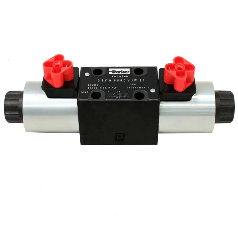
D1VW 系列方向阀为NG06 规格的三油腔阀体方向控制阀,采用湿式电磁铁直动操控。能在极小、节能的压降下,提供高达80 l/min 的最大极限流量。
该系列方向阀具有十分多样的阀芯型式选项,能满足任何类型的液压回路设计。
D1VW 系列方向阀可有8W 电磁铁、阀芯位置监控、防爆、户外使用条件(表面防护) 及不同的电气接口等多种类型供选择,以满足不同工况要求,相关的资料将在后续的章节中提供。
技术参数
| 一般参数 | |||||||
| 结构型式 | 滑阀型方向控制阀 | ||||||
| 操控装置 | 电磁铁 | ||||||
| 规格 | DIN NG06 / CETOP 03 / NFPA D03 | ||||||
| 安装界面 | DIN 24340 A6 / ISO 4401 / CETOP RP 121-H / NFPA D03 | ||||||
| 安装姿态 | 任意, 水平安装优先 | ||||||
| 环境温度 | [ºC] | -25…+50 | |||||
| MTTFD 值 (平均无故障工作时间) | [years] | 150 | |||||
| 重量 | [kg] | 1.5 (单电磁铁), 2.1 (双电磁铁) | |||||
| 液压参数 | |||||||
| 最高工作压力 | [bar] | P, A, B: 350, T: 210 (DC), 140 (AC) | |||||
| 工作油液 | 液压油, 符合 DIN 51524…51525 | ||||||
| 油液温度 | [ºC] | -25…+70 | |||||
| 油液粘度 容许范围 推荐范围 | [cSt] / [mm2/s] | 2.8…400 | |||||
| [cSt] / [mm2/s] | 30…80 | ||||||
| 过滤要求 | ISO 4406 (1999): 18/16/13 | ||||||
| 最大流量 | [l/min] | 80 (详见换向极限曲线) | |||||
| 泄漏量,50 bar 时 | [ml/min] | 每流道最大 10,随阀芯型式而异; 对 008, 009 型阀芯,每流道最大 15 | |||||
| 静 / 动态参数 | |||||||
| 阶跃响应 | 见表列响应时间 | ||||||
| 电气参数 | |||||||
| 负荷率 ED (相对得电时间) | 100%,注意:线圈温度可能高达 150°C | ||||||
| 最高开关频率 | [1/h] | 15000 (软切换型阀不适用) | |||||
| 防护等级 | IP 65, 符合 EN 60529 (在正确安插好电插头的状态下) | ||||||
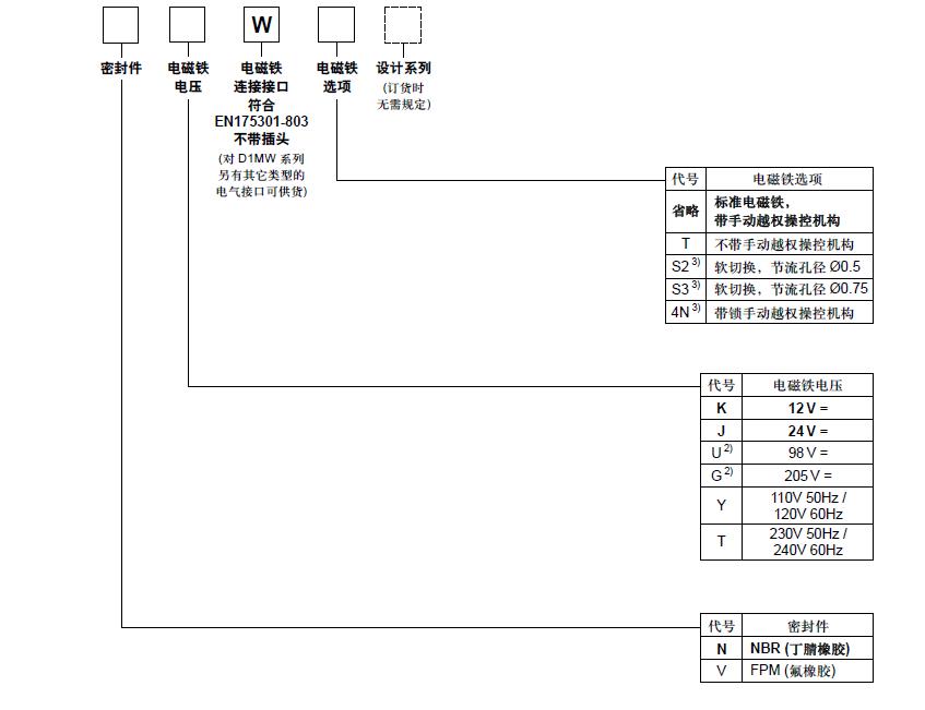
| 电磁铁电压代号 | K | J | U | G | Y | T | |
| 电源电压 | [V] | 12 V = | 24 V = | 98 V = | 205 V = | 110, 50Hz / 120, 60Hz | 230, 50Hz / 240, 60Hz |
| 容许的电源电压波动 | [%] | ±10 | ±10 | ±10 | ±10 | ±5 | ±5 |
| 消耗电流 吸持状态 切换过程 | [A] | 2.72 2.72 | 1.29 1.29 | 0.33 0.33 | 0.13 0.13 | 0.6 / 0.55 | 0.3 / 0.27 1.25 / 1.2 |
| [A] | 2.5 / 2.4 | ||||||
| 消耗功率 吸持状态 切换过程 | [W] | 32.7 32.7 | 31 | 31.9 31.9 | 28.2 28.2 | 70 / 70 [VA] | 70 / 70 [VA] |
| [W] | 31 | 280 / 290 [VA] | 280 / 290 [VA] | ||||
| 电磁铁连接形式 | 接线插口符合 EN 175301-803, 电磁铁标识按 ISO 9461 (代号 W) | ||||||
| 接线最小截面积 | [mm2] | 3 x 1.5 (推荐) | |||||
| 接线最大长度 | [m] | 50 (推荐) | |||||
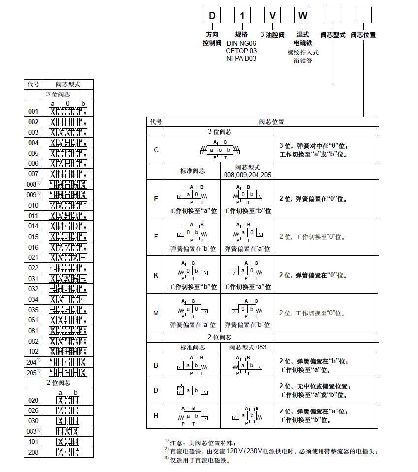
订货代号
D1VW 系列DC与AC 电磁方向阀的换向极限。对于阀芯位置代号为“F”或“M”的阀,只能工作在70% 换向极限以下的工况。图线所示的数值适用于油液粘度为40mm2/s,且流经油口A 和B 的流量相等的工况。若油口A 和B 的流量不等,则换向极限将比图示的数值明显减小。为了避免流量超过阀的换向极限,可以在油口P 内插入安装一个节流塞。
相关商品


标签 D1VW002CNJW91, Parker, 电磁阀, 换向阀, parker电磁阀, 派克电磁换向阀, 派克换向阀SD500A06, 派克单向阀, 美国派克电磁阀官网, 派克球阀官网, 派克电磁阀型号, 派克球阀和截止阀, 派克汉尼汾电磁阀, 派克高压截止阀